Guide to Glass Surface Grinding and Polishing
What are the concepts of glass surface grinding and polishing?
Glass surface grinding and polishing are two closely linked yet fundamentally distinct precision machining processes within the cold processing of glass. Together, they form a complete surface modification chain, progressing from a "rough blank" to an "optically transparent surface." The core distinction lies in their objectives: grinding is for "geometric shaping and damage control," while polishing is for "damage removal and interface reconstruction."
1.Glass Surface Grinding
Concept Definition:
Grinding utilizes loose or fixed hard abrasives to perform mechanical cutting between a rigid carrier (the grinding plate or lap) and the glass surface. Through the rolling, scratching, and crushing actions of the abrasives, material is rapidly removed from the glass surface layer to achieve precise geometric shapes, dimensional tolerances, and a specified surface roughness.
Core Physical Essence:
Brittle Fracture Dominance: Abrasive particles pressed onto the glass surface generate Hertzian cracks. The lateral propagation of these cracks leads to the fragmentation and chipping of the material.
Three-Body Wear Mechanism: Abrasives roll freely between the grinding plate and the glass, constantly changing the direction of their cutting edges.
Isotropic Removal: On a macroscopic scale, material removal is uniform and does not produce directional textures.
Technical Objectives:
Shaping: Imparting precise curvature radii, flatness, and thickness dimensions to the glass blank.
Defect Removal: Eliminating deep damage layers left by previous processes (e.g., sawing, molding).
Polishing Preparation: Establishing a uniform and controllable subsurface damage layer that allows for stable material removal during the subsequent polishing stage.
Key Parameters:
Abrasives: Silicon Carbide (SiC), Aluminum Oxide (Al₂O₃), Diamond. Grit sizes are progressively reduced from coarse (e.g., #80) to fine (e.g., #2000).
Carrier/Lap: Cast iron, copper, or resin laps. The lap's hardness dictates its ability to constrain the glass's shape.
MPressure, Rotation Speed, Coolant.
Typical Surface State:
Surface appears uniformly matte or frosted.
Roughness (Ra): 0.1 – 1.0 μm (depending on the final abrasive grit size).
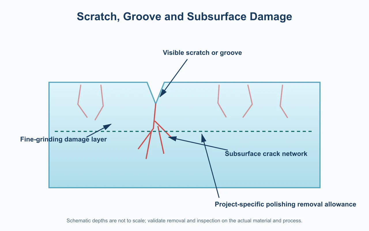
Presence of a controlled-depth subsurface crack layer (typically 1/3 to 1/2 of the abrasive particle size).
2.Glass Surface Polishing
Concept Definition:
Polishing employs soft abrasives, which are either as hard as or, more commonly, softer than the glass itself, on a flexible carrier (the polishing pad or tool). It removes minute amounts of material from the pre-ground surface through mechanical, chemical, or physicochemical interactions. The goal is to completely eliminate the subsurface damage layer left by grinding and to achieve an ultimately smooth, defect-free, mirror-like, and transparent surface with atomic-level smoothness.
Core Physical Essence:
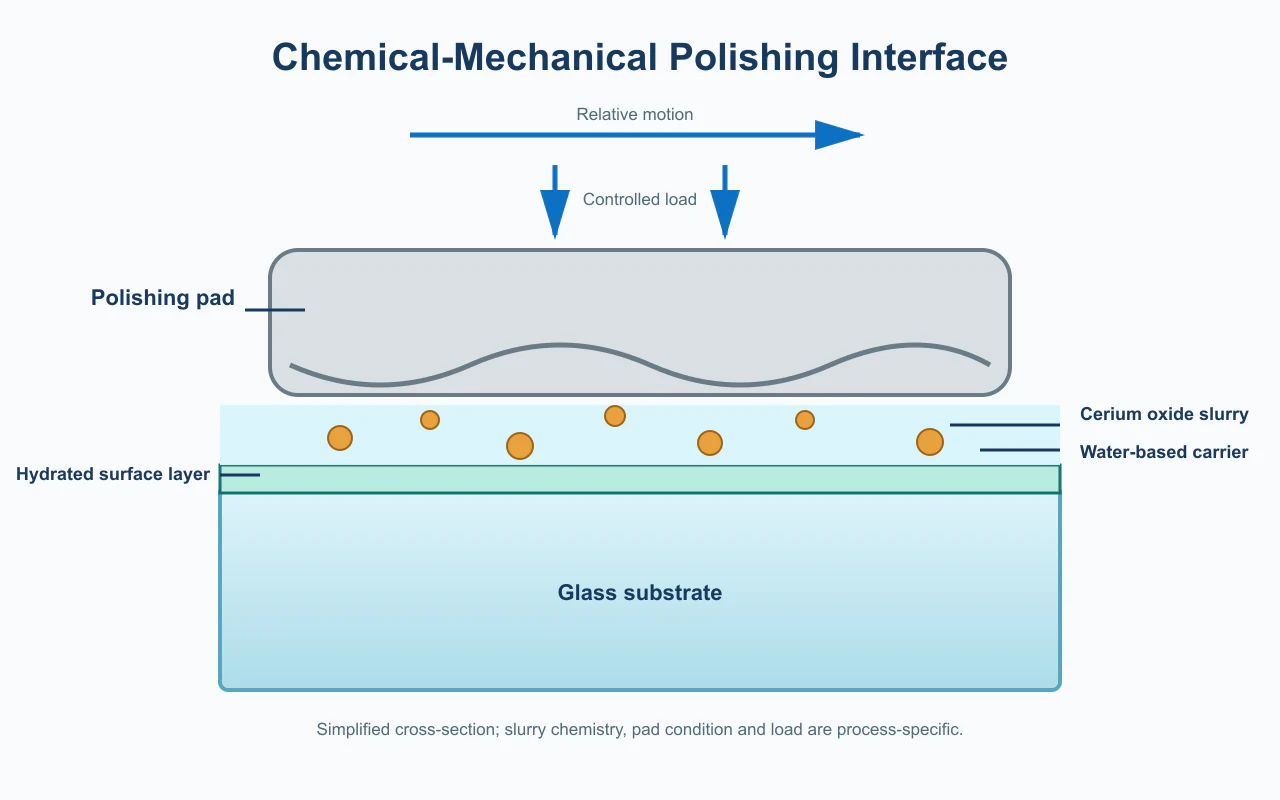
Plastic Flow and Chemical Bonding Dominance: Classic theories, such as the Rebinder effect, suggest that water molecules in the polishing slurry hydrolyze the glass surface, forming a hydrated silicagel layer (a softened layer). This layer is then mechanically sheared away by the polishing abrasives. This is a chemo-mechanical synergy.
Two-Body or Single-Body Wear: Abrasives become embedded in or adhere to the polishing pad, functioning with fixed cutting edges.
No New Cracks: Material removal occurs on a nanometer scale, far below the threshold for brittle fracture.
Technical Objectives:
Complete Removal of Subsurface Damage: Ensuring the inherent strength and optical performance of the glass.
Achieving a Transparent Mirror Finish: Surface roughness reduced to Ra < 1 nm, with no visible scratches or haze to the naked eye.
Precise Figure Retention: Modifying the surface without compromising the geometric accuracy established during the grinding stage.
Key Parameters:
Abrasives: Cerium Oxide (CeO₂) – considered the "gold standard" for glass polishing, Zirconium Oxide (ZrO₂), Iron Oxide (Jeweler's Rouge).
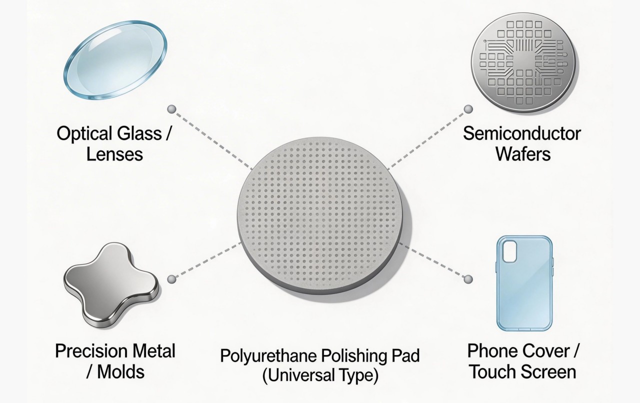
Carrier/Polishing Pad: Polyurethane pads, pitch tools, felt cloth. Pitch polishing is the ultimate method for precision optical polishing.
Slurry pH Value, Concentration, Flow Rate; Temperature, Pressure.
Typical Surface State:
Surface is completely transparent with a mirror-like reflection.
Roughness (Ra): 0.5 – 2.0 nm (for optical grades), potentially reaching atomic flatness (detectable by AFM).
No subsurface damage layer present (or damage depth less than 1/10 of the light wavelength).
The Principles of Glass Surface Grinding and Polishing
Although both are surface finishing processes, glass surface grinding and polishing have fundamentally different material removal mechanisms: grinding is a mechanical fragmentation process dominated by brittle fracture, while polishing is an atomic-scale removal process involving plastic flow through chemo-mechanical synergy. Together, they form a complete physical transformation chain from a "rough surface" to a "smooth mirror finish."
Principles of Glass Surface Grinding
The core principle of grinding is that hard abrasives, pressed into the glass surface under pressure, cause material to be brittlely removed through the propagation of lateral cracks.
1.Indentation Fracture Mechanics Model
When an abrasive particle (with hardness significantly greater than that of glass) is pressed onto the glass surface by the grinding plate, a Hertzian stress field is generated at the point of contact.
Once the stress exceeds the glass's elastic limit, a plastic indentation (central deformation zone) forms first.
Upon continued loading, radial/median cracks develop beneath the plastic zone, extending vertically downward.
During unloading, lateral cracks propagate from the base of the plastic zone towards the surface. When these lateral cracks extend to the surface or connect with adjacent cracks, glass fragments are dislodged.
2. Three-Body Wear Mechanism
Loose abrasives roll freely between the grinding plate and the glass, constantly changing the direction of their cutting edges and points of contact.
Each rolling action generates a new cycle of indentation, crack propagation, and material chipping.
The abrasive particle size determines the indentation depth and crack dimensions. The material removal rate is approximately proportional to the abrasive particle size multiplied by the pressure and relative velocity.
3. Principles of Geometric Shaping
The macroscopic shape of the rigid grinding plate (made of cast iron, copper, or resin) is transferred to the glass surface through a replication effect.
Protruding areas on the glass surface experience higher pressure and thus faster material removal; recessed areas experience lower pressure and slower removal.
Ultimately, the glass surface conforms to the conjugate shape of the grinding plate surface (whether flat, spherical, or aspherical).
4. Subsurface Damage Layer
Grinding inevitably introduces a subsurface crack layer, with a depth typically ranging from one-third to one-half of the abrasive particle size.
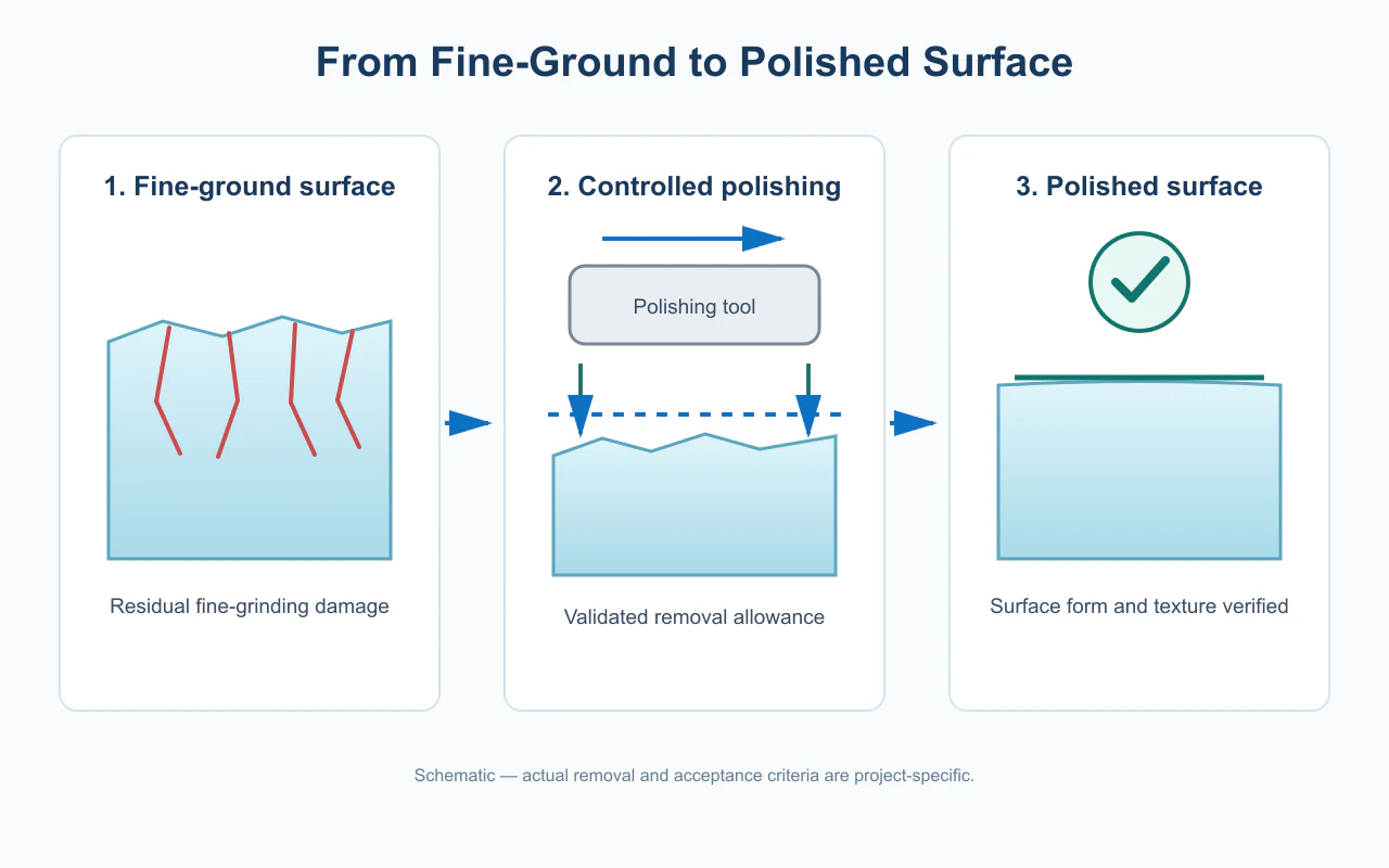
This is a necessary cost to prepare for subsequent polishing—coarse grinding establishes the shape, while fine grinding transforms deep damage into a shallow, controllable layer.
Principles of Glass Surface Polishing
The core principle of polishing is the plastic removal of material at the nanometer scale, facilitated by chemical softening, to completely eliminate subsurface damage.
1. The Rebinder Effect (Chemo-Mechanical Synergy) – The Cornerstone of Polishing Theory
Step 1 (Chemical Hydrolysis): Water molecules in the polishing slurry hydrolyze the silica network (≡Si–O–Si≡) on the glass surface via the reaction:
≡Si–O–Si≡ + H₂O → ≡Si–OH + HO–Si≡
This generates a hydrated silica gel layer (a softened layer) on the glass surface, approximately 1–10 nm thick. Its hardness and elastic modulus are significantly lower than that of the bulk glass.
Step 2 (Mechanical Shearing): Polishing abrasives (e.g., cerium oxide, zirconium oxide) become embedded in or adhere to the polishing tool (e.g., pitch, polyurethane) and, acting as fixed or semi-fixed grains, shear across the glass surface, mechanically removing the softened gel layer.
Step 3 (Cyclic Regeneration): After the softened layer is removed, a fresh glass surface is exposed. This new surface undergoes hydrolysis again, followed by another shearing action. This cycle repeats, enabling continuous and uniform material removal.
2. Plastic Flow and Tribochemistry
Under nanoscale contact pressures, the stress on the glass surface exceeds its yield point but remains below the threshold for brittle fracture, leading to plastic flow (analogous to metal cutting).
Solid-state reactions occur between the polishing abrasive and the glass surface in microscopic zones of high temperature and pressure, forming a reaction layer that is subsequently carried away. Cerium oxide (CeO₂) exhibits a unique chemical affinity for silicate glass, resulting in significantly higher polishing efficiency compared to other abrasives.
3. Principles of Surface Planarization
The polishing tool is flexible, allowing it to conform to the macroscopic shape of the glass while applying higher pressure to microscopic protrusions
The softened layer is removed more quickly from protruding areas, while it remains longer in recessed areas, creating a positive feedback loop between pressure and removal rate.
This process ultimately yields an atomically smooth surface (Ra < 1 nm).
4. Complete Removal of the Damage Layer
The amount of material removed during polishing must exceed the depth of the subsurface cracks left by the preceding grinding stage.
A standard criterion for optical components is that the depth of material removed by polishing should be at least three times the depth of the grinding-induced cracks, ensuring that no subsurface damage remains.
Core Processing Capabilities of Glass Surface Grinding and Polishing
Glass surface grinding and polishing are not merely "individual processes" but rather a deterministic manufacturing system that trades material removal for geometric precision and surface quality. Their core processing capabilities can be systematically defined from the following three dimensions:
1. Core Mechanism: Chemical-Mechanical Wear and Plastic Flow
Tool: Utilizes soft polishing wheels (such as felt, flannel, polyurethane) and polishing paste/powder (mainly composed of cerium oxide CeO₂ or iron oxide).
Process: This is a finer and more complex surface interaction process than grinding.
Chemical Action: Cerium oxide in the polishing paste undergoes a mild hydration reaction with silicon dioxide (SiO₂) on the glass surface under localized high temperature and pressure generated by friction, forming a hydrated cerium silicate gel layer that is softer than the glass itself.
Mechanical Action: The soft polishing wheel continuously "smears" and "removes" this gel layer. As the gel layer is constantly removed, fresh glass surfaces are exposed and continue to react with the polishing agent. This cycle repeats, achieving material removal and surface smoothing at the molecular level.
Plastic Flow: Under localized high pressure and frictional heat, molecules on the outermost glass surface undergo minute viscous flow, filling microscopic scratches and depressions.
2. Key Elements:
Choice of Polishing Agent: Cerium oxide has become the "gold standard" for glass polishing due to its excellent chemical activity, appropriate hardness, and self-sharpening properties.
Pressure, Speed, and Time: Require precise balancing. Too little pressure results in ineffective material removal; too much pressure can generate heat and new scratches.
Ultimate Goal: Through polishing, the light-scattering surface of the edge is transformed into a light-transmitting surface, restoring the glass's inherent transparency. For the highest standard optical edges, surface roughness can reach the nanometer level.
3. Special Process: Flame Polishing
Primarily used for soda-lime glass and high-borosilicate glass; not suitable for tempered glass.
Principle: Utilizes a high-temperature flame (oxygen-fuel gas) to instantly heat the glass edge above its softening point (approximately 700-800°C).
Process: Under the influence of surface tension, the molten glass surface layer flows and re-spreads, filling microscopic scratches and defects. It then rapidly cools, forming a smooth, bright surface akin to a "fire-polished" finish.
Characteristics: Fast speed, low cost, and excellent gloss can be achieved. However, it cannot alter the geometric shape and requires high operator experience; improper control can easily lead to glass deformation or stress introduction.
Common Questions & Answers about Glass Edge Grinding and Polishing Services
I. Surface Scratches and Deep Scratches
Phenomenon: After grinding or polishing, the glass surface exhibits visible linear depressions, or microscopically, the damage layer from the previous process is not completely removed.
Cause Analysis:
Excessive Abrasive Grit Size Jump: The depth of the damage layer from the previous grinding stage exceeds the removal capability of the subsequent abrasive, leading to "residual scratches."
Coarse Abrasive Contamination in Fine Processes: Inadequate equipment cleaning or failure of the polishing slurry circulation filtration system allows coarse particles to be carried into the fine grinding or polishing stage.
Poor Condition of Lap or Polishing Pad: Loss of lap flatness, aging or hardening of the polishing pad, or entrapment of hard particles.
Improper Operation: Hard friction between the glass and the lap during handling, or excessive processing pressure causing abrasives to embed into the glass.
Solutions:
Strictly implement the "Grit Size Matching" principle, ensuring the damage layer from the previous step is completely removed by the next. Typically, the removal amount should be 1/3 to 1/2 of the previous abrasive particle size.
Establish strict equipment cleaning protocols, with thorough cleaning between different grit size processes. The polishing slurry circulation system requires high-precision filtration (e.g., 5-10μm filter elements).
Regularly dress the laps, replace polishing pads, and maintain a service life log.
Optimize part handling procedures, using auxiliary tools or automated loading/unloading.
II. Edge Roll-Off and Edge Rounding (Edge Effect)
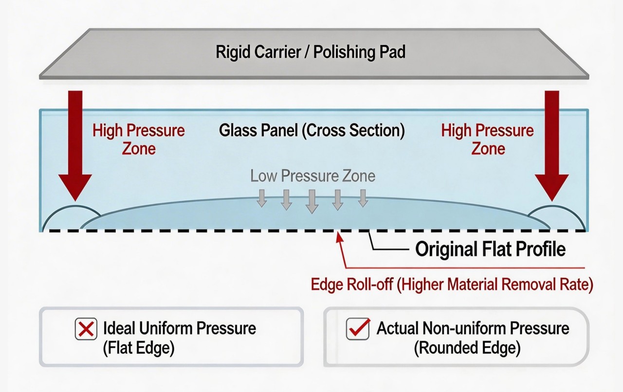
Phenomenon: The material removal rate at the glass edge is greater than at the center, resulting in edge sagging, thinning, or rounded corners.
Cause Analysis:
Uneven Pressure Distribution: During processing, the pressure at the edge region is higher than at the center (especially with rigid carriers), leading to a faster removal rate at the edge.
Lap/Polishing Plate Deformation: Edge wear or warpage of the lap after prolonged use.
Improper Oscillation Trajectory: The relative motion between the workpiece and the lap fails to adequately cover the edge area, causing localized over-processing.
Uneven Pad Compression: The edge of the polishing pad compresses more easily under pressure, leading to increased contact pressure.
Solutions:
Employ "conditioning rings" or "centering plates" to dress the lap online during processing, maintaining its flatness.
Optimize the motion trajectory to ensure the edge of the workpiece has dwell time on the lap comparable to the center area.
For precision optical components, use "dual-axis planetary motion" or "swing-arm processing" to improve edge uniformity.
Consider using soft polishing pads combined with back-pressure control to minimize edge effects.
III. Haze, Orange Peel, and Micro-Roughness
Phenomenon: The polished surface appears cloudy, exhibits an orange peel texture, or shows microscopic undulations under intense light, resulting in insufficient transparency.
Cause Analysis:
Insufficient Polishing Time: Failure to completely remove the subsurface damage layer from the previous grinding stage.
Improper Polishing Slurry Parameters: Abrasive concentration too low, pH value deviating from the optimal range (affecting chemo-mechanical action), or slurry temperature too high causing localized drying.
Incorrect Polishing Pad Selection or Condition: Pad hardness too high or too low, grooves clogged and ineffective, or pad aged and lost its elasticity.
Mismatched Process Parameters: Improper pressure-speed combination fails to establish a stable "hydrodynamic lubrication" state, leading to intermittent contact between abrasives and the glass.
Solutions:
Determine the minimum required polishing time for the process through "time-removal rate" curve experiments.
Establish a real-time monitoring system for polishing slurry concentration, pH value, temperature, and flow rate. The optimal pH for cerium oxide slurry is typically 6-8.
Select matching polishing pads (polyurethane, non-woven, pitch, etc.) based on glass type and precision requirements, and establish a replacement schedule.
Optimize parameters like pressure, speed, and eccentricity through Design of Experiments (DOE) to find the optimal process window.
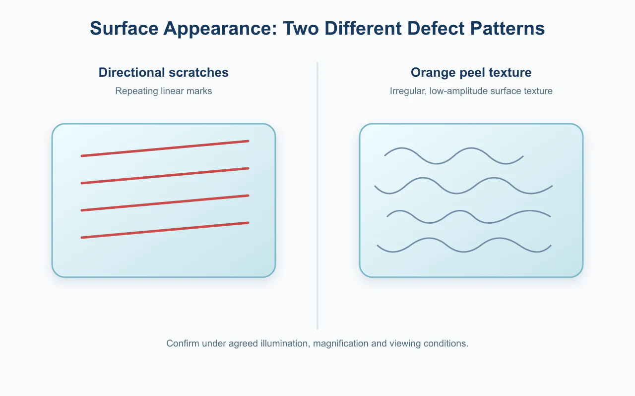
IV. Directional Scratches and Orange Peel
Phenomenon: The surface exhibits fine, directional lines or an irregular orange peel texture.
Cause Analysis:
Uneven Abrasive Distribution: Clumping or sedimentation of abrasives in the slurry leads to localized scratching by large particles.
Equipment Vibration: Vibration from the spindle or drive system leaves periodic patterns on the glass surface.
Repetitive Motion Trajectory: The relative motion trajectory between the workpiece and lap is monotonous, failing to achieve "isotropic" grinding/polishing.
Poor Polishing Pad Groove Design: Uneven slurry flow leads to localized dry friction.
Solutions:
Continuously stir the grinding/polishing slurry to prevent sedimentation. Check dispersion before use.
Regularly inspect equipment spindle runout and vibration levels (typically required to be ≤0.01mm).
Employ compound motion trajectories (e.g., planetary gear mechanisms) to ensure uniform processing from all directions on the glass surface.
Optimize polishing pad groove design (spiral, concentric circles, grid) to ensure uniform slurry distribution and drainage.
V. Surface Contamination and Corrosion (White Spots/Mildew)
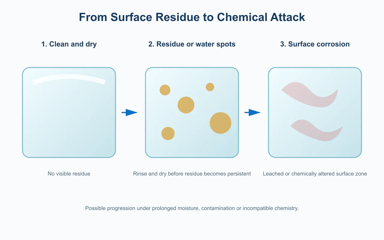
Phenomenon: White spots, haze, or corrosive spots appearing on the surface after polishing, sometimes developing over time.
Cause Analysis:
Inadequate Cleaning: Residual polishing slurry (especially cerium oxide) or grinding slurry dries on the surface, forming stubborn stains.
Water Quality Issues: High hardness or impurities in the cleaning water, or residues from the final rinse causing water spots.
Improper Storage Environment: High humidity or acidic atmosphere leading to ion exchange or mildew on the glass surface.
Polishing Slurry Formulation Issues: Certain additives or impurities chemically reacting with the glass.
Solutions:
Establish a multi-stage cleaning process: Rough cleaning (deionized water + detergent) → Fine cleaning (pure water) → Dehydration (ethanol/isopropanol) → Drying.
Use high-purity deionized water (resistivity > 18MΩ·cm) for the final rinse.
Control storage environment: Temperature 20-25℃, humidity <45%, free from acidic gases. Use acid-free packaging paper and sealed bags.
Regularly analyze polishing slurry composition, avoiding additives corrosive to the glass.
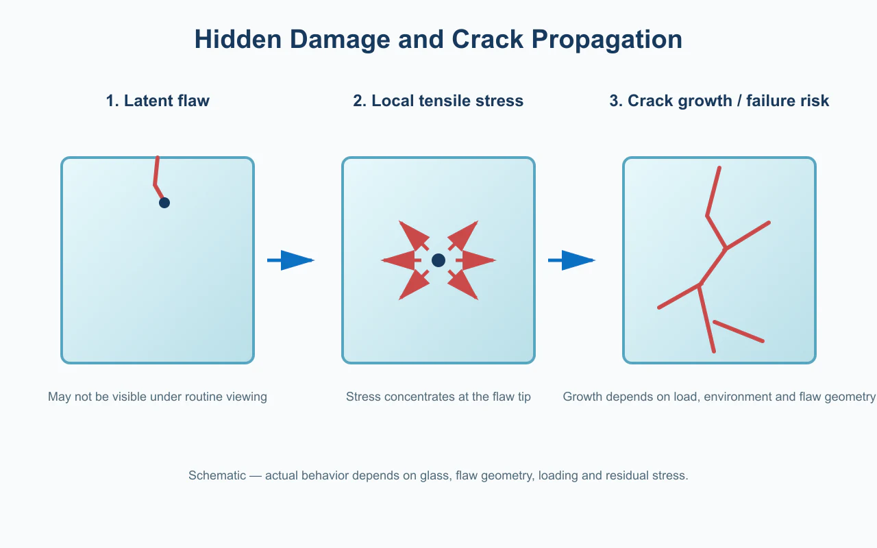
VI. Stress Concentration and Micro-Cracks (Potential Strength Degradation)
Phenomenon: The glass appears macroscopically defect-free after processing but fails strength tests or cracks during subsequent thermal processing or coating.
Cause Analysis:
Incomplete Removal of Grinding Damage Layer: The polishing stage fails to completely eliminate the subsurface micro-crack layer left by grinding.
Thermal Stress from Localized Overheating: Excessive polishing pressure or speed causes localized frictional heating, generating thermal stress or even micro-cracks.
Improper Edge Treatment: Micro-cracks generated during cutting or edge grinding are not removed by polishing.
Solutions:
Regularly inspect the subsurface damage layer depth using confocal microscopy or etching methods to verify sufficient polishing removal.
Control polishing pressure and speed to avoid localized overheating. For precision optics, use intermittent polishing or cooling systems.
Perform fine polishing on edges after beveling to eliminate micro-cracks induced by cutting.
Glass Surface Grinding and Polishing Service Company Technical Standard
Document Number: GSP-STD-2025
Applicable Departments: Deep Processing Division, Quality Department, Process Engineering Department
Version: 1.0
Effective Date: January 1, 2025
1.1 Purpose
This standard aims to establish unified technical specifications, quality acceptance criteria, and process control requirements for our company's glass surface grinding and polishing services, ensuring that delivered products achieve industry-leading levels of surface flatness, smoothness, optical performance, and mechanical strength, thereby meeting the differentiated needs of various customers for glass surface treatment.
1.2 Scope of Application
This standard applies to all glass surface planar processing services undertaken by our company, covering glass types including soda-lime glass, high borosilicate glass, aluminosilicate glass, glass-ceramics, fused silica, optical glass, and ultra-thin electronic glass. The processing forms covered include single-sided grinding and polishing, double-sided grinding and polishing, continuous polishing, and pitch polishing. The application areas encompass optical windows, display covers, precision substrates, instrument viewing windows, decorative panels, and semiconductor substrates.
2.1 Definition of Surface Grades (from lowest to highest)
For Grade S1, designated as the coarse ground surface, a single stage of coarse grinding is performed, resulting in a uniformly matte surface with no gloss and a surface roughness Ra of ≤1.6μm. Flatness is not specified, and typical applications include backside thinning, non-functional surfaces, and bonding surfaces. Grade S2, the fine ground matte finish, involves coarse grinding followed by fine grinding, producing a fine matte texture with a smooth hand feel and no visible grinding marks. It achieves a surface roughness Ra of ≤0.8μm and a flatness of ≤0.1mm per 100mm, commonly used for industrial viewing windows, home appliance panels, and back panels. Grade S3, the semi-transparent polished finish, is produced through coarse grinding, fine grinding, and initial polishing, resulting in a semi-transparent appearance with faint light transmission. It achieves a surface roughness Ra of ≤0.05μm and a flatness of ≤5μm per 50mm, suitable for instrument dials, decorative glass, and frosted finishes with localized transparency. Grade S4, the fully transparent polished finish, uses coarse grinding, fine grinding, and precision polishing to achieve complete transparency with no visible defects. It attains a surface roughness Ra of ≤5nm and a flatness of ≤1μm per 50mm, typically applied to general optical windows, touch panels, and protective covers. Grade S5, the optical grade polished finish, involves ultra-precision polishing combined with pitch polishing, delivering extreme transparency with uniform interference fringes. It achieves a surface roughness Ra of ≤1nm and a flatness of ≤λ/4 at 632.8nm, used for precision optical components, laser windows, and wafer substrates.
2.2 Processing Accuracy Standards
For thickness tolerance, S1 and S2 grades require ±0.05mm, S3 grade requires ±0.03mm, and S4 and S5 grades require ±0.01mm, with measurement performed using micrometers and thickness gauges. For parallelism, S1 and S2 grades require ≤0.03mm per 100mm, S3 grade requires ≤0.01mm per 100mm, and S4 and S5 grades require ≤0.003mm per 100mm, measured using dial indicators and collimators. For flatness, S1 and S2 grades require ≤0.05mm per 100mm, S3 grade requires ≤0.02mm per 100mm, and S4 and S5 grades require ≤0.001mm per 100mm, inspected using optical flats and laser interferometers. Localized flatness is not specified for S1 and S2 grades, while S3 grade requires ≤1μm per mm and S4 and S5 grades require ≤0.1μm per mm, measured using profilometers and interference microscopes. Transmittance at 550nm is not applicable for S1 and S2 grades, while S3 grade requires ≥85% and S4 and S5 grades require ≥91% for uncoated surfaces, measured using spectrophotometers.
2.3 Subsurface Damage Control
Subsurface damage is defined as the micro-crack layer generated beneath the glass surface during grinding, which must be completely removed through subsequent polishing. For S1 and S2 grades, residual damage depth of ≤10μm is permissible. For S3 grade, residual damage depth of ≤3μm is permissible. For S4 and S5 grades, no residual damage is permissible, requiring complete removal verified through cross-sectional microscopy. Validation is performed by inspecting one piece per batch using cross-sectional microscopy or hydrofluoric acid etching methods.
3.1 Core Equipment
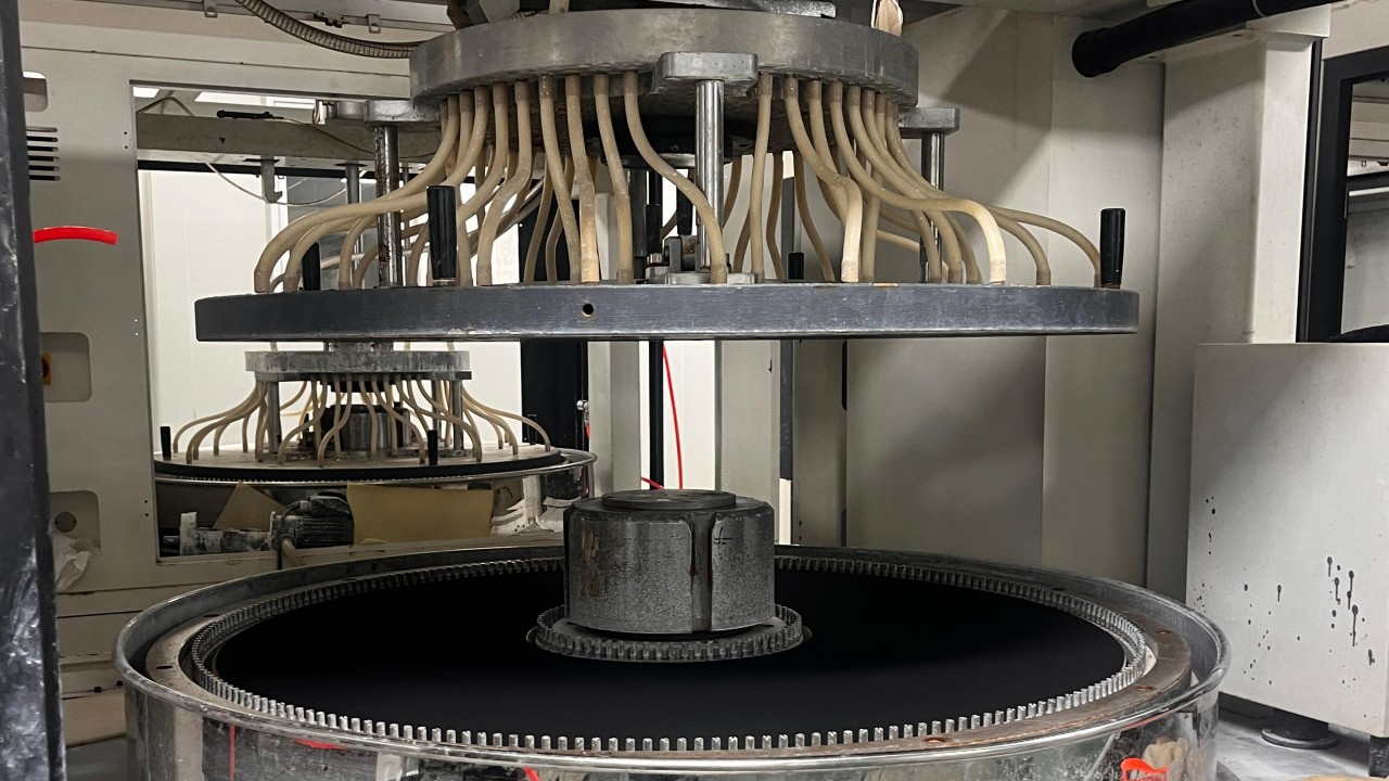
Double-sided grinding and polishing machines are required to feature independently driven upper and lower plates with closed-loop pressure control, capable of processing workpieces up to φ500mm for high-volume production of parallel plane thin plates. Single-sided polishing machines must employ oscillating or planetary motion with temperature control systems, capable of processing workpieces up to φ800mm for thick plates, irregularly shaped parts, and high-precision single-sided processing. Continuous polishing machines utilize pitch laps with temperature control to achieve surface form accuracy PV ≤ λ/10 for optical-grade ultra-precision polishing. Ultrasonic cleaning lines must consist of multiple tanks with final drying achieving cleanliness level Class 100, ensuring no residue and no water spots for all post-polishing cleaning operations.
3.2 Laps and Polishing Pads
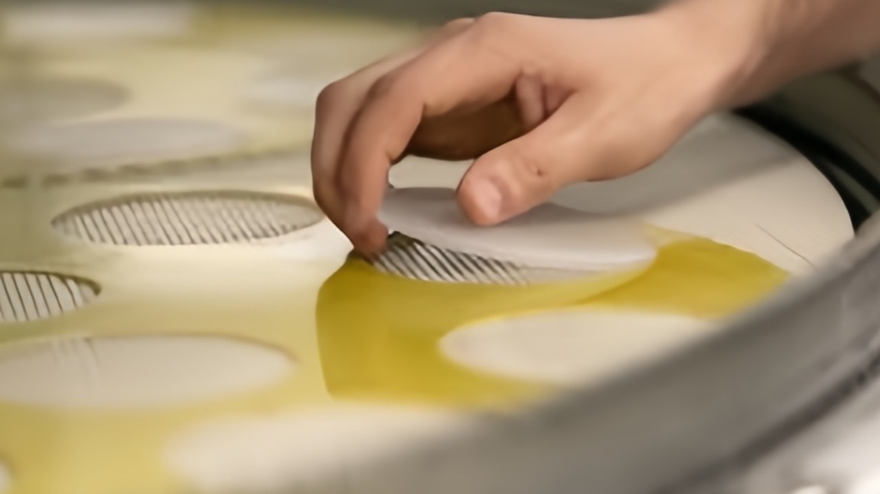
For coarse and medium grinding, cast iron laps with hardness HB180-220 and flatness ≤0.02mm per 300mm are required, with dressing performed every 8 hours. For fine grinding, copper or tin laps are used for precision thickness control. Polishing pads are categorized by type: polyurethane polishing pads serve as general-purpose pads with moderate hardness suitable for S3 and S4 grades; non-woven polishing pads offer softness suitable for curved surfaces or thin sheet precision polishing; pitch polishing laps provide optical-grade self-leveling characteristics used for S5 grade. The dressing cycle requires inspection before each batch, with mandatory dressing or replacement every 50 batches or when quality fluctuations occur.
3.3 Abrasives and Polishing Slurries
Grinding abrasives follow a grit size chain: coarse grinding uses silicon carbide (SiC) in grit sizes F60 to F120; medium grinding uses silicon carbide or aluminum oxide (Al₂O₃) in grit sizes F150 to F280; fine grinding uses aluminum oxide or boron carbide in grit sizes W20 to W10. The grit size progression principle requires that the grit size ratio between adjacent processes does not exceed 1:1.5 to ensure complete removal of the damage layer from the previous process. For polishing powders, S3 and S4 grades use high-purity cerium oxide (CeO₂) with D50 1.0-2.0μm and purity ≥99.5%; S5 grade uses zirconium oxide or colloidal silica with particle size ≤0.1μm for chemical mechanical polishing (CMP). Polishing slurry control parameters include concentration typically at 5-10% for general use and 2-5% for optical grade, monitored by hydrometer; pH value maintained at 6.0-8.0 for cerium oxide systems, tested and adjusted daily; circulation filtration using 5μm filter elements for continuous filtration, replaced weekly.
3.4 Environmental Requirements
Temperature control requires processing workshops maintained at 20-22°C for optical-grade processing and 18-26°C for general processing. Humidity control requires 45±5% relative humidity to prevent excessive evaporation of polishing slurries. Cleanliness levels require ISO Class 8 for S1 to S3 grades and ISO Class 7 or higher for S4 and S5 grades. Vibration control requires optical-grade equipment to be installed on active vibration isolation bases with environmental vibration meeting VC-C grade (≤6μm/s).
4.1 Incoming Quality Control (IQC)
Raw glass sheets are measured for thickness, dimensions, and initial warp, with all data recorded. Initial surface quality is inspected visually, and sheets with severe scratches, stones, or bubbles are rejected. Samples are retained from each batch for traceability purposes.
4.2 First Article Inspection (FAI)
First article inspection must be performed for each production batch or after any process parameter adjustment, with comprehensive inspection covering thickness and parallelism measured using micrometers at multiple points, surface roughness measured using contact stylus profilometers or white light interferometers, surface form accuracy inspected using optical flats or laser interferometers for S4 and S5 grades, and appearance inspected under bright light to verify no scratches, orange peel, haze, or water spots. Batch production may only commence after the quality inspector signs off on the first article approval.
4.3 In-Process Quality Control (IPQC)
Regular patrol inspections are conducted every 2 hours with random sampling of in-process products to monitor thickness and appearance. Process parameters including pressure, rotational speed, slurry flow rate, and temperature are continuously recorded, with automatic alarms triggered when values exceed control limits. Lap and polishing pad conditions are checked every 4 hours, with online dressing performed when necessary. Post-cleaning inspection involves random sampling to verify cleaning effectiveness, ensuring no water spots or residue remain.
4.4 Final Quality Control (FQC)
Appearance is subject to 100% visual inspection under standard D65 light source at a distance of 30cm for 3-5 seconds to verify no scratches, grinding marks, orange peel, haze, white spots, or water spots, with no visible defects in the clear aperture. Dimensional inspection follows AQL sampling level 1.0 for thickness and flatness measurements. Roughness inspection requires at least 5 pieces per batch, with every piece of S4 and S5 grades inspected individually. Stress inspection uses polariscopes for random sampling to ensure processing has not introduced harmful residual stress, with optical path difference ≤20nm/cm.
4.5 Subsurface Damage Verification (Mandatory for S4 and S5 Grades)
The verification method involves cross-sectional polishing followed by hydrofluoric acid etching and microscopic examination. Inspection frequency requires at least one piece per batch or after each process change. The acceptance standard requires no visible micro-crack extensions.
5.1 Surface Protection
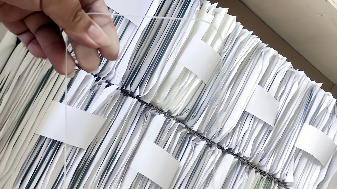
For isolation, each piece of glass must be interleaved with neutral release film or electrostatic adsorption protective film, with direct contact between glass surfaces strictly prohibited. For cleanliness, the final step before packaging is ionized air dust removal performed in a clean environment. For edge protection, four corners must be fitted with PE foam edge protectors to prevent impact damage during handling.
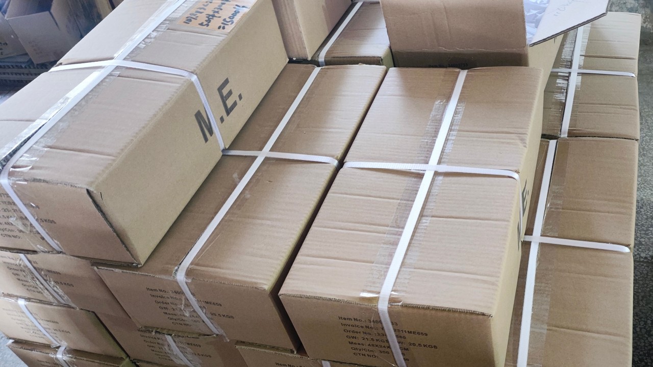
5.2 Packaging Methods
For S1 and S2 grades, packaging requires neutral paper isolation with corrugated boxes or EVA separators, ensuring moisture protection and crush resistance. For S3 grade, packaging requires electrostatic film with polyethylene foam separators and reinforced corrugated boxes, ensuring moisture protection, shock resistance, and labeling indicating "optical surface." For S4 and S5 grades, packaging requires vacuum packaging or sealed cleanroom bags with custom wooden crates and vibration-damping supports, ensuring moisture protection, shock resistance, temperature-controlled transport, and tilt monitoring.
5.3 Accompanying Documentation
Each delivered batch must include a product certificate of conformance with inspector signature, a shipping inspection report containing measured values for critical dimensions, roughness, and surface form, a material certificate if required by the customer, and the final confirmed processing drawings indicating the surface grade.
6.1 Traceability System
Each finished glass piece is traceable through batch numbers or laser-engraved traceability codes to the raw material supplier and batch number, the grinding and polishing machine numbers and operators, the process parameter records for each operation including pressure, speed, time, and consumable batch numbers, and the inspection records and inspectors for each operation.
6.2 Engineering Changes
Any changes involving surface grade, tolerances, or polishing results require a written change notification from the customer. Our company implements a four-step process of internal change evaluation, sample validation, customer approval, and batch transition. Change records must be archived for at least 5 years for future reference.
7.1 Delivery Commitment
For S1 and S2 grades, the standard delivery cycle is 5 business days with an expedited cycle of 3 business days subject to evaluation. For S3 grade, the standard delivery cycle is 7 business days with an expedited cycle of 5 business days subject to evaluation. For S4 grade, the standard delivery cycle is 10 business days with an expedited cycle of 7 business days subject to evaluation. For S5 grade, the standard delivery cycle is 15 business days with an expedited cycle of 10 business days subject to evaluation, as optical grade requires separate scheduling. The cycle is calculated from the date when raw materials are ready, drawings are confirmed, and advance payment is received.
7.2 Quality Assurance
Our company commits that delivered products will be 100% compliant with this standard and customer drawing requirements. If product defects such as surface scratches, uneven polishing, or dimensional non-conformance occur due to our processing, we will provide unconditional rework or replacement and bear the resulting direct losses. For optical-grade products, surface form interference pattern measurement reports are provided as delivery verification documentation.
Advantages and Disadvantages of Glass Surface Grinding and Polishing
Glass surface grinding and polishing are closely interrelated processes, typically used in combination to achieve the transformation from a rough blank to a mirror-like surface. The following systematic analysis examines these processes from four dimensions: process characteristics, quality outcomes, cost efficiency, and technical limitations.
I. Advantages and Disadvantages of the Grinding Process
Grinding is the rough machining stage that uses relatively coarse abrasives to rapidly remove excess glass material and correct shape.
Grinding offers high material removal efficiency, with coarse grinding capable of removing 50–100μm per minute. This allows rapid elimination of excess material and deformation left by previous processes such as cutting or molding, making it suitable for high-volume thickness sizing and initial flatness adjustment. It has strong shape correction capability, effectively correcting glass warp and parallelism errors to lay the foundation for subsequent polishing. The process can handle a variety of hard and brittle materials, including high-hardness optical glass and glass-ceramics. The cost is relatively low, as abrasives such as silicon carbide and aluminum oxide are inexpensive, and equipment investment and maintenance costs are lower than those of high-precision polishing machines. Additionally, through precision grinding, highly accurate flatness and parallelism can be achieved, reaching levels of 0.01mm per 100mm, thereby establishing a precise geometric baseline.
Disadvantages:
Grinding inevitably introduces a subsurface damage layer beneath the glass surface, generating micro-cracks and residual stress that can reach depths of one to three times the abrasive particle size. This damage must be completely removed by subsequent polishing; otherwise, glass strength and optical performance will be significantly compromised. The surface roughness after grinding is poor, with coarse grinding achieving Ra values of 1–3μm, resulting in a uniform matte finish with no transparency. Even after fine grinding, Ra values of 0.2–0.5μm still produce a frosted, non-transparent appearance. There is a risk of abrasive particle embedding, where coarse abrasives may become embedded in the glass surface and, if cleaning is insufficient, contaminate downstream processes. Cross-contamination between different grit sizes can lead to quality issues such as scratches. Additionally, mechanical pressure during grinding may introduce processing stress, requiring special attention to pressure parameters, especially for thin glass plates.
II. Advantages and Disadvantages of the Polishing Process
Polishing is the finishing stage that builds upon the ground surface, using fine-grained polishing powders to achieve a transparent, smooth surface through chemo-mechanical interaction.
Advantages:
Polishing can achieve optical-grade surface quality, with surface roughness Ra values as low as 1nm or even below, resulting in complete transparency and a mirror-like finish. It eliminates the subsurface damage layer left by grinding, restoring the intrinsic strength of the glass. High-precision polishing methods, such as pitch polishing, enable surface form accuracy to reach λ/10 or better at 632.8nm, meeting the demanding requirements of interferometers, laser windows, and other high-end optical applications. The process leverages chemo-mechanical synergy, where chemical components in the polishing slurry, such as cerium oxide, undergo hydrolysis reactions with the glass surface to form a softened layer that is then mechanically removed, achieving atomic-scale material removal and producing an ideal surface free of scratches and damage. Polishing is applicable to a wide range of materials, from ordinary soda-lime glass to ultra-hard fused silica and glass-ceramics, by adjusting the type of polishing powder and process parameters to match different glass characteristics.
Disadvantages:
The material removal rate during polishing is extremely low, typically only 0.1–0.5μm per minute, which is just 1/100 to 1/1000 of the grinding rate. This low efficiency makes polishing the bottleneck of the entire production line. The process window is narrow and control is difficult, as parameters such as pressure, rotational speed, temperature, pH value, and concentration are highly sensitive, with even minor fluctuations potentially causing quality problems. Skilled and experienced technicians are required for setup and adjustment. Consumable costs are high, with high-purity cerium oxide polishing powder being significantly more expensive than silicon carbide, often costing 10 to 20 times as much. Polishing pads, such as polyurethane and pitch, are consumed quickly and require regular replacement. Optical-grade polishing also necessitates expensive in-process monitoring equipment. Polishing is prone to defects such as orange peel, haze, directional scratches, water spots, and uneven polishing, making yield control challenging. Defects often require rework or lead to scrap, increasing costs. Maintaining dimensional accuracy is difficult, as prolonged polishing can cause edge roll-off, warpage, and other geometric distortions. For thin glass plates, improper pressure control during polishing can easily lead to deformation. Finally, cleaning requirements are extremely stringent, as polishing powder adsorbed on the surface must be completely removed; otherwise, it will dry and form stubborn stains. This necessitates multi-stage pure water cleaning and dehydration drying, adding to post-processing costs.
III. Synergistic Relationship Between Grinding and Polishing
Grinding and polishing are not isolated processes but rather complementary stages in a process chain. Grinding provides high material removal rates of 50–100μm per minute, enabling rapid thickness sizing, while polishing offers low removal rates of only 0.1–0.5μm per minute, focusing on fine surface finishing. Grinding results in surface roughness Ra values ranging from 0.2 to 3μm, providing the foundational flatness, whereas polishing achieves Ra values from 1nm to 0.05μm, delivering the final mirror-like finish. Grinding generates a deep subsurface damage layer, while polishing completely eliminates that damage layer. Grinding establishes the basic geometric form, and polishing preserves or slightly refines that form. The cost structure differs significantly: grinding involves lower equipment costs and inexpensive abrasives, while polishing requires higher equipment investment and expensive consumables. The key principle is to allocate material removal appropriately to balance overall cost, ensuring that grinding leaves sufficient stock for polishing and that polishing completely removes the subsurface damage introduced by grinding.
IV. Process Selection Decision Guide
For applications requiring backside thinning or non-functional surfaces, a coarse or medium grinding-only process is recommended as it offers the lowest cost without requiring transparency. For industrial viewing windows and home appliance panels, fine grinding combined with light polishing is suitable, balancing cost with basic transparency. For touch panels and protective covers, precision grinding followed by fine polishing achieves full transparency, a defect-free appearance, and a smooth tactile feel. For precision optical components, ultra-precision grinding combined with optical-grade pitch polishing is necessary to achieve both high surface form accuracy and superior surface quality. For ultra-thin flexible glass, thinning grinding followed by gentle polishing is recommended, with careful control of stress and deformation being the primary considerations.
Contact Us
Your feedback fuels our growth, and your questions drive our solutions.
We value your feedback, inquiries, and suggestions. Please feel free to get in touch with us
General inquiries
Please contact us via sales@bo-glass.com, and we will reply to you as soon as possible.
Interested to work with us
Drop your resume at info@bo-glass.com
and we will get back to you shortly.
We uses the contact information you provide to us to contact you about our relevent content, products, and services.