
What is cathode magnetron sputtering?
In 1852, Grove in the UK and, later in 1858, Plücker in Germany independently observed cathode erosion during gas discharge experiments in glow discharge tubes. By 1877, the sputtering process was applied to mirror production, using rare gas ions to bombard metal surfaces. Over the next century, researchers refined the technique, culminating in the maturation of cathode sputtering technology by 1955.
Magnetron sputtering enhanced this traditional approach by incorporating magnetic fields to confine electrons near the target, increasing plasma density and ionization efficiency. This results in higher deposition rates and improved film quality.
What is the sputtering principle?
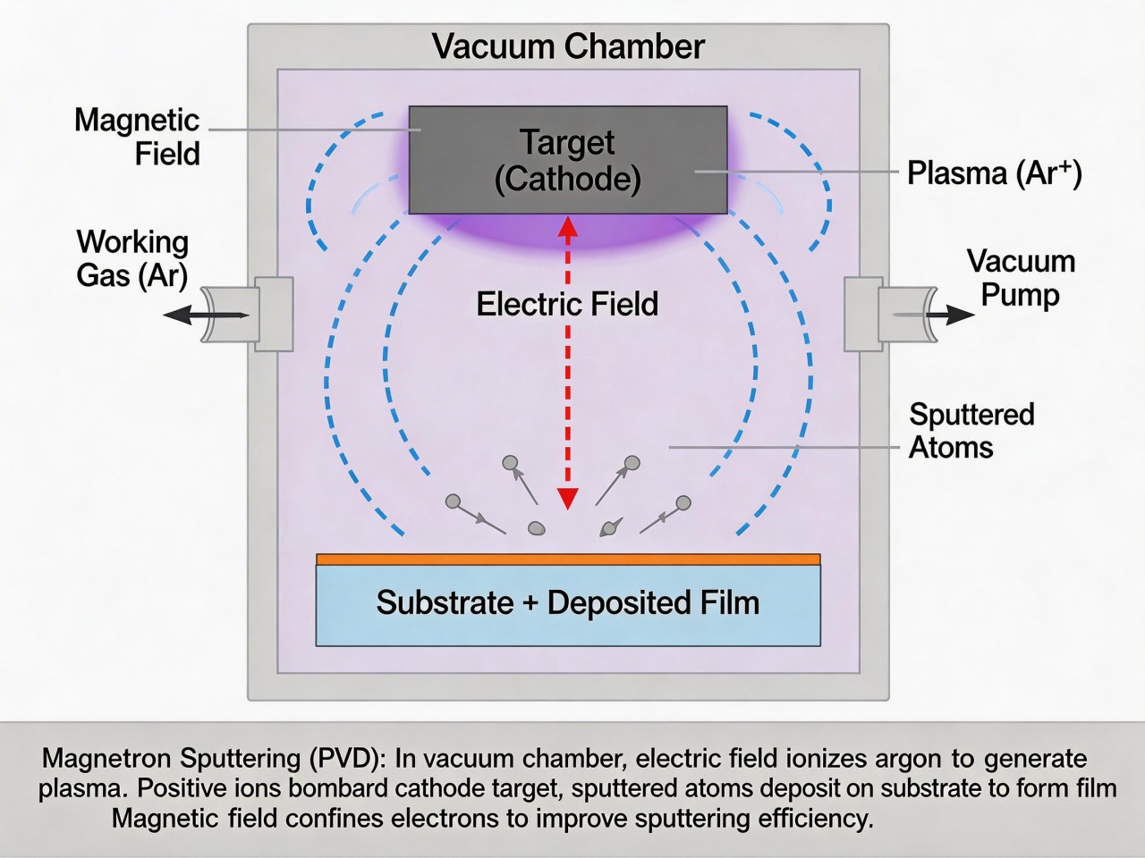
The electric field generated by the cathode voltage interacts with the magnetic field from permanent magnets, forming a perpendicular electromagnetic field. Under this influence, argon ions are accelerated toward the cathode, gaining significant energy in the potential drop zone near the cathode. These high-energy ions bombard the target material, transferring kinetic energy to neutral atoms or molecules on the target surface, causing them to eject. These ejected particles are then deposited onto the substrate, such as glass, forming a thin film layer.
Secondary electrons generated during the sputtering process reenter the plasma region, contributing to further ionization and maintaining the supply of argon ions. Once their energy is depleted, these electrons are attracted to the anode and expelled from the vacuum chamber. This process efficiently deposits high-energy particles onto the substrate while recycling electrons, forming the fundamental principle of magnetron sputtering.

Figure 4-14 Principle diagram of magnetron sputtering
Magnetron Sputtering Process
The efficiency of energy transfer depends on the relative mass of the ions and the target atoms. The energy required for atoms to leave the target surface depends on the latent heat of evaporation of the target material. In reactive sputtering, where oxygen or nitrogen is used as the working gas, more energy is needed to break chemical bonds, resulting in lower efficiency. The sputtering yield, defined as the number of atoms ejected per ion, can vary for different materials and ion energies.
Sputtering is not an efficient process, as most of the energy is converted into heat and absorbed by the target. This necessitates water cooling to prevent the target material from bending or melting. Despite these challenges, sputtering remains an ideal method for depositing thin and uniform multilayers on large glass surfaces.
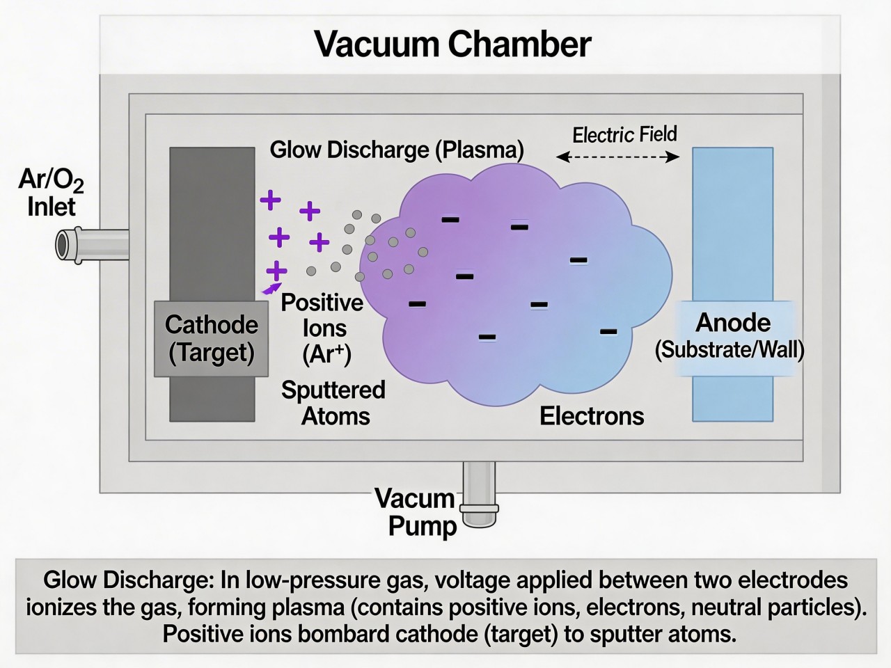
Figure 4-15 Schematic diagram of glow discharge
Magnetic Field, Plasma Density, and Efficiency in Magnetron Sputtering
The sputtering rate in magnetron sputtering depends heavily on the effective ion density within the plasma. To achieve a dense plasma, a perpendicular electric field (E) and magnetic field (B) configuration, known as an “EB field,” is employed. The magnetic field, generated by permanent magnets positioned behind the target, is aligned parallel to the target surface. This arrangement enhances ionization efficiency and plasma density.
Electrons in the plasma are accelerated away from the cathode under the influence of the electric field. As they pass through the magnetic field, they experience a perpendicular force, causing them to move in circular trajectories. With each circular motion, the electrons gain energy from the magnetic field. These high-energy electrons collide with gas atoms or sputtered atoms, ionizing them and generating additional ions. This cascade effect significantly increases plasma density, enhancing sputtering rates and improving deposition efficiency.
Optimization of the magnetic field configuration is crucial for maximizing ion generation and achieving higher plasma densities. A denser plasma enables faster sputtering rates and greater coating efficiency. This optimization has dramatically improved the productivity of magnetron sputtering, especially in the manufacturing of coated glass.
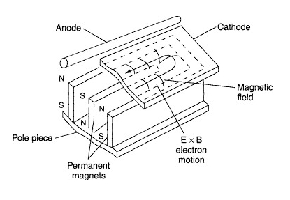
Figure 4-16 Magnetic field and electron motion trajectory on the surface of magnetron sputtering target
What are the materials used for magnetron sputtering?
1.Sputtering Gases
Sputtering gases are divided into two main types: working gases and reactive gases.
(1) Working Gases
When selecting a working gas, key considerations include:
- High sputtering yield.
- Chemical inertness to the target material.
- Cost-effectiveness and availability.
- High purity.
Inert gases such as argon, helium, and neon are commonly used. While helium and neon achieve higher sputtering rates for the same ion energy, argon is preferred in industrial applications due to its availability, lower cost, and satisfactory performance. Argon eliminates the need for complex and expensive material vaporization processes, making it the standard working gas in industrial sputtering.
(3) Gas Pressure
- Higher pressure increases discharge current and reverse scattering, causing energetic particles to decelerate due to collisions. This reduces the energy of sputtered particles, which convert to heat upon reaching the substrate.
- Lower pressure has the opposite effect, reducing collision rates but potentially impacting plasma density.
To maintain uniform coatings, the vacuum system must have a high pumping speed to remove residual gases and contaminants rapidly. Pressure gradients near the discharge area should be avoided to prevent non-uniform discharge and uneven film deposition.
(2) Reactive Gases
Oxide and nitride films are most commonly produced, with oxygen and nitrogen as the primary reactive gases in industrial applications.
(4) Gas Contamination
- Residual water vapor in the vacuum chamber.
- Desorbed gases from chamber walls due to ion bombardment.
- Adsorbed gases on the target material.
- Leaks in the sputtering chamber.
- Impurities in the working gas itself.
Most contamination can be minimized through:
- High-quality vacuum technology.
- Adequate pre-sputtering to remove surface contaminants.
- Using high-purity gases to reduce external doping.
By carefully managing the gas selection, pressure, and contamination, magnetron sputtering can produce high-purity, uniform films suitable for advanced applications in optical coatings, electronics, and protective layers.
Table 4-6 Sputtering yields of various elements obtained using inert gas ions (500 eV)
| Element | He | Ne | Ar | Kr | Xe |
| Be | 0.24 | 0.42 | 0.51 | 0.48 | 0.35 |
| C | 0.07 | 0.12 | 0.13 | 0.17 | |
| Al | 0.16 | 0.73 | 1.05 | 0.96 | 0.82 |
| Si | 0.13 | 0.48 | 0.5 | 0.5 | 0.42 |
| Ti | 0.07 | 0.43 | 0.51 | 0.48 | 0.48 |
| V | 0.06 | 0.48 | 0.65 | 0.62 | 0.63 |
| Cr | 0.17 | 0.99 | 1.18 | 1.39 | 1.55 |
| Mn | 1.39 | 1.43 | |||
| Mn | 1.9 | ||||
| Bi | 6.64 | ||||
| Fe | 0.15 | 0.88 | 1.1 | 1.07 | 1 |
| Fe | 0.63 | 0.84 | 0.77 | 0.88 | |
| Co | 0.13 | 0.9 | 1.22 | 1.08 | 1.08 |
| Ni | 0.16 | 1.1 | 1.45 | 1.3 | 1.22 |
| Ni | 0.99 | 1.33 | 1.06 | 1.22 | |
| Cu | 0.24 | 1.8 | 2.35 | 2.35 | 2.05 |
| Cu | 1.35 | 2 | 1.91 | 1.91 | |
| Cu(III) | 2.1 | 2.05 | 3.9 | ||
| Cu | 1.2 | ||||
| Ce | 0.08 | 0.68 | 1.1 | 1.12 | 1.04 |
| Y | 0.05 | 0.46 | 0.68 | 0.66 | 0.48 |
| Zr | 0.02 | 0.38 | 0.65 | 0.51 | 0.58 |
| Nb | 0.03 | 0.33 | 0.6 | 0.55 | 0.53 |
| Mo | 0.03 | 0.48 | 0.8 | 0.87 | 0.87 |
| Mo | 0.24 | 0.64 | 0.59 | 0.72 | |
| Ru | 0.57 | 1.15 | 1.27 | 1.2 | |
| Rh | 0.06 | 0.7 | 1.3 | 1.43 | 1.38 |
| Pd | 0.13 | 1.15 | 2.08 | 2.22 | 2.23 |
| Ag | 0.2 | 1.77 | 3.12 | 3.27 | 3.32 |
| Ag | 1 | 1.7 | 2.4 | 3.1 | |
| Ag | 3.06 | ||||
| Sm | 0.05 | 0.69 | 0.8 | 1.09 | 1.28 |
| Gd | 0.03 | 0.48 | 0.83 | 1.12 | 1.2 |
| Dy | 0.03 | 0.55 | 0.88 | 1.15 | 1.29 |
| Er | 0.03 | 0.52 | 0.77 | 1.07 | 1.07 |
| Hf | 0.01 | 0.28 | 0.7 | 0.8 | |
| Ta | 0.01 | 0.28 | 0.57 | 0.87 | 0.88 |
| W | 0.01 | 0.28 | 0.57 | 0.91 | 1.01 |
| Re | 0.01 | 0.37 | 0.87 | 1.25 | |
| Os | 0.01 | 0.37 | 0.87 | 1.27 | 1.33 |
| Ir | 0.01 | 0.43 | 1.01 | 1.35 | 1.56 |
| Pt | 0.03 | 0.63 | 1.4 | 1.82 | 1.98 |
| Au | 0.07 | 1.08 | 2.4 | 3.06 | 7.01 |
| Au | 1.1 | 1.3 | 2.5 | 7.7 | |
| Pb | 1.1 | 2.7 | |||
| Th | 0 | 0.28 | 0.62 | 0.98 | 1.05 |
| U | 0.45 | 0.85 | 1.3 | 0.81 | |
| Sb | 2.83 | ||||
| Sb(固体) | 1.2 | ||||
| Sb(液体) | 1.4 |
2.Sputtering Materials (Targets)
(1)Types of Sputtering Materials
(2)Installation Methods for Sputtering Targets
Planar Mounting
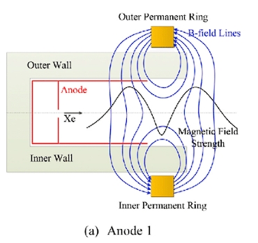

Figure 4-19 Schematic diagram of rotating target structure
Rotational Mounting
Table 4-7 Sputtering yields of argon ions of different energies colliding with various materials
| Target Voltage (V) | 200.0 | 600.0 | 1000.0 | 2000.0 | 5000.0 | 10000.0 |
| Ag (Atoms/Ion) | 1.6 | 3.4 | - | - | 8.8 | - |
| Al (Atoms/Ion) | 0.35 | 1.2 | - | - | 2.0 | - |
| Au (Atoms/Ion) | 1.1 | 2.8 | 3.6 | 5.6 | 7.9 | - |
| C (Atoms/Ion) | 0.05 | 0.02 | - | - | - | - |
| Cr (Atoms/Ion) | 0.7 | 1.3 | - | - | - | - |
| Cu (Atoms/Ion) | 1.1 | 2.3 | 3.2 | 4.3 | 5.5 | - |
| Fe (Atoms/Ion) | 0.5 | 1.3 | 1.4 | 2.0 | 2.5 | - |
| Ge (Atoms/Ion) | 0.5 | 1.2 | 1.5 | 2.0 | 3.0 | - |
| Mo (Atoms/Ion) | 0.4 | 0.9 | 1.1 | - | 1.5 | 2.2 |
| Nb (Atoms/Ion) | 0.25 | 0.65 | - | - | - | - |
| Ni (Atoms/Ion) | 0.7 | 1.5 | 2.1 | - | - | - |
| Pb (Atoms/Ion) | 1.0 | 2.4 | - | - | - | - |
| Pt (Atoms/Ion) | 0.6 | 1.6 | - | - | - | - |
| Si (Atoms/Ion) | 0.2 | 0.5 | 0.6 | 0.9 | 1.4 | - |
| Ta (Atoms/Ion) | 0.3 | 0.6 | - | 1.1 | - | 1.05 |
| Ti (Atoms/Ion) | 0.2 | 0.6 | - | 1.1 | 1.7 | 2.1 |
| W (Atoms/Ion) | 0.3 | 0.6 | - | - | 1.1 | - |
| Zr (Atoms/Ion) | 0.3 | 0.75 | - | - | - | - |
| LiF (Molecules/Ion) | - | - | - | 1.3 | 1.8 | 2.2 |
| CdS (Molecules/Ion) | 0.5 | 1.2 | - | - | - | - |
| GaAs (Molecules/Ion) | 0.4 | 0.9 | - | - | - | - |
| PbTe (Molecules/Ion) | 0.6 | 1.4 | - | - | - | - |
| SiC (Molecules/Ion) | - | 0.45 | - | - | - | - |
| SiO₂ (Molecules/Ion) | - | - | 0.13 | 0.4 | - | - |
| Al₂O₃ (Molecules/Ion) | - | - | 0.04 | 0.11 | - | - |
Magnetron Sputtering Production Methods and Processes
1.Batch Production Method
Glass substrates are inspected manually upon arrival at the workshop. Approved substrates are washed and dried using a cleaning machine, then mounted into loading frames, one sheet per frame. The frames are loaded onto a transport cart and pushed into the sputtering chamber for coating.
After the chamber is sealed, vacuum pumping, pre-sputtering, and sputtering processes commence. Pre-sputtering is performed with the cathodes directed toward a pre-sputtering plate to remove impurities. Once the specified current density and voltage are reached, the ion energy is sufficient for sputtering onto the substrate. The cathode assembly moves over the substrate to deposit a layer, then resets to the pre-sputtering plate for subsequent layers. Typically, three layers are applied: an oxide layer, a metallic layer, and another oxide layer.
After sputtering, the chamber is vented, and the frames are removed manually. Coated glass undergoes quality inspection, and protective anti-scratch layers are applied before packaging and storage.
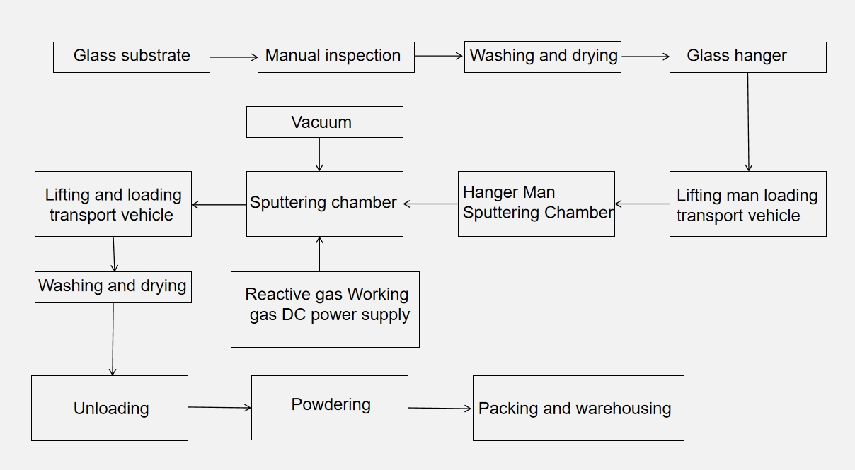
Figure 4-20 Intermittent production process flow
2.Continuous Production Method
(a) Horizontal Continuous Production
Glass substrates are loaded using cranes or vacuum suction systems, cleaned, dried, and inspected before entering the vacuum system.
The substrates pass through sequential vacuum chambers for sputtering:
- Chamber I: Reactive sputtering with oxygen to deposit an oxide layer.
- Chamber II: Sputtering with inert gases (e.g., nitrogen) for a metallic layer.
- Chamber III: Reactive sputtering with oxygen for a final oxide layer.
Intermediary isolation zones with gas controls ensure no cross-contamination between chambers.
After coating, substrates pass through an exit system for cleaning, inspection, and packaging.
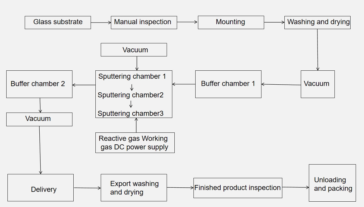
Figure 4-21 Horizontal continuous production process flow
(b) Vertical Continuous Production

Figure 4-22 Vertical continuous production process of Low-E glass
Features of Magnetron Sputtering for Coated Glass Production
Excellent Film Thickness Control and Repeatability
Strong Adhesion Between Film and Substrate
Capability to Produce Specialized Films
High Sputtering Rates
High Film Purity
Key Considerations for Magnetron Sputtering of Coated Glass
Fresh Glass
Thorough Pre-Coating Cleaning
Avoid Moisture During Transport and Storage
No Bare-Hand Contact After Cleaning
Glow Discharge Cleaning
Precise Control of Reactive Gases
Stable Process Parameters
Comparison Between Evaporation and Sputtering Methods
Table 4-8: Comparison Between Evaporation and Sputtering Methods for Thin Film Preparation
| Aspect | Evaporation | Sputtering |
|---|---|---|
| Vapor Generation Phase |
|
|
| Transport Phase |
|
|
| Condensation Phase |
|
|
Contact Us
Your feedback fuels our growth, and your questions drive our solutions.
We value your feedback, inquiries, and suggestions. Please feel free to get in touch with us
General inquiries
Please contact us via sales@bo-glass.com, and we will reply to you as soon as possible.
Interested to work with us
Drop your resume at info@bo-glass.com
and we will get back to you shortly.
We uses the contact information you provide to us to contact you about our relevent content, products, and services.